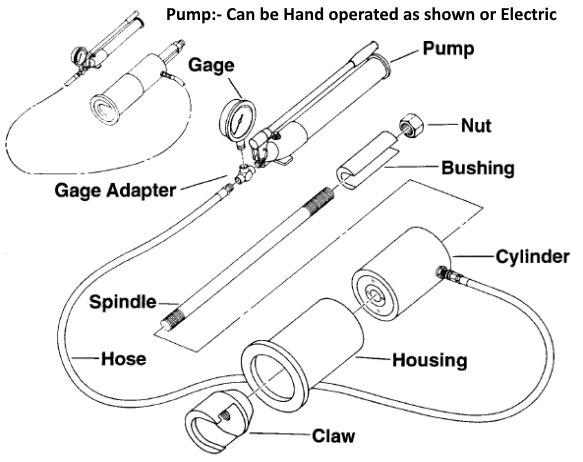
The pull tester consists of two assemblies: the hydraulic portion which includes the cylinder, gage, pump, hose and adapter; and the mechanical portion which includes the claw, housing, U-shaped bushing, spindle and nut.
With the bushing removed, the claw can be slid over the pull collar which has been installed with the stabilizer. When the housing are cylinder are raised, the bushing can be inserted between the nut and the cylinder. The nut is then tightened to take up slack.
The pump is then actuated to raise cylinder pressure, pulling the stabilizer slightly out of the hole through the bearing plate.
Maximum gage reading at slip indicates the holding force. The device can be used for slip loads up to 12 US tons (10.9 metric tons).


